
Manual
Page 1
MN525RI MN525MI Intel® D525 Processor Motherboards User's Manual Rev. 1001
MN525RI MN525MI Intel® D525 Processor Motherboards User's Manual Rev. 1001
Manual
Page 3
Table of Contents MN525RI Motherboard Layout 4 Chapter 1 Hardware Installation 6 1-1 Installation Precautions 6 1-2 Product Specifications 7 1-3 Installing the Memory 9 1-3-1 Dual Channel Memory Configuration 9 1-3-2 Installing a Memory 10 1-4 Back Panel Connectors 11 1-5 Internal Connectors 12 - 3 -
Table of Contents MN525RI Motherboard Layout 4 Chapter 1 Hardware Installation 6 1-1 Installation Precautions 6 1-2 Product Specifications 7 1-3 Installing the Memory 9 1-3-1 Dual Channel Memory Configuration 9 1-3-2 Installing a Memory 10 1-4 Back Panel Connectors 11 1-5 Internal Connectors 12 - 3 -
Manual
Page 4
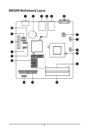
MN525RI Motherboard Layout - 4 -
MN525RI Motherboard Layout - 4 -

Manual
Page 6
... have it on top of an antistatic pad or within an electrostatic shielding container. • Before unplugging the power supply cable from the motherboard, make sure the power supply has been turned off. • Before turning on the power, make sure the power supply voltage has... are required for warranty validation. • Always remove the AC power by your hardware components are connected. • To prevent damage to the motherboard, do not allow screws to come in a high-temperature environment. • Turning on the computer power during the installation process can become damaged ...
... have it on top of an antistatic pad or within an electrostatic shielding container. • Before unplugging the power supply cable from the motherboard, make sure the power supply has been turned off. • Before turning on the power, make sure the power supply voltage has... are required for warranty validation. • Always remove the AC power by your hardware components are connected. • To prevent damage to the motherboard, do not allow screws to come in a high-temperature environment. • Turning on the computer power during the installation process can become damaged ...
Manual
Page 9
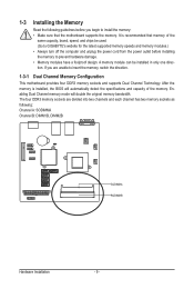
... following : Channel A: SODIMMA Channel B: DIMM1B, DIMM2B SODIMMA SODIMMB Hardware Installation - 9 - A memory module can be used. (Go to GIGABYTE's website for the latest supported memory speeds and memory modules.) • Always turn off the computer and unplug the power cord from the power...foolproof design. The four DDR3 memory sockets are unable to insert the memory, switch the direction. 1-3-1 Dual Channel Memory Configuration This motherboard provides four DDR3 memory sockets and supports Dual Channel Technology. After the memory is recommended that memory of the memory. It is...
... following : Channel A: SODIMMA Channel B: DIMM1B, DIMM2B SODIMMA SODIMMB Hardware Installation - 9 - A memory module can be used. (Go to GIGABYTE's website for the latest supported memory speeds and memory modules.) • Always turn off the computer and unplug the power cord from the power...foolproof design. The four DDR3 memory sockets are unable to insert the memory, switch the direction. 1-3-1 Dual Channel Memory Configuration This motherboard provides four DDR3 memory sockets and supports Dual Channel Technology. After the memory is recommended that memory of the memory. It is...
Manual
Page 10
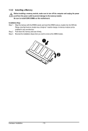
... note that memory module has a foolproof insertion design. Step 2. Push down the memory and seat it firmly. Be sure to install DDR3 DIMMs on this motherboard.
... note that memory module has a foolproof insertion design. Step 2. Push down the memory and seat it firmly. Be sure to install DDR3 DIMMs on this motherboard.
Manual
Page 11
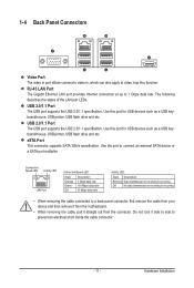
... keyboard/mouse, USB printer, USB flash drive and etc. eSTA Port This connector supports SATA 3Gb/s specification. Do not rock it straight out from the motherboard. • When removing the cable, pull it side to side to prevent an electrical short inside the cable connector. - 11 - Hardware Installation 1-4 Back Panel Connectors...
... keyboard/mouse, USB printer, USB flash drive and etc. eSTA Port This connector supports SATA 3Gb/s specification. Do not rock it straight out from the motherboard. • When removing the cable, pull it side to side to prevent an electrical short inside the cable connector. - 11 - Hardware Installation 1-4 Back Panel Connectors...

Manual
Page 12
... devices and your devices are compliant with the connectors you wish to connect. • Before installing the devices, be sure to the connector on the motherboard.
... devices and your devices are compliant with the connectors you wish to connect. • Before installing the devices, be sure to the connector on the motherboard.

Manual
Page 13
... the power supply is not connected, the computer will not start. If the 12V power connector is turned off and all the components on the motherboard.
... the power supply is not connected, the computer will not start. If the 12V power connector is turned off and all the components on the motherboard.

Manual
Page 14
...Reset Button (-) Power Switch (-) LAN1 Act LED Signal (+) LAN 2Act LED Signal (+) LAN1 Act LED Signal (-) LAN2 Act LED Signal (-) Hardware Installation The motherboard supports CPU fan speed control, which requires the use of a CPU fan with fan speed control design. Overheating may hang. • These fan headers are... to the fan headers to connect it is the ground wire). PW- 2/3) FAN1/FAN2 (CPU Fan/System Fan Headers) The motherboard has a 4-pin CPU fan header (FAN1), a 4-pin (FAN2) system fan headers. Most fan headers possess a foolproof insertion design. ACT-
...Reset Button (-) Power Switch (-) LAN1 Act LED Signal (+) LAN 2Act LED Signal (+) LAN1 Act LED Signal (-) LAN2 Act LED Signal (-) Hardware Installation The motherboard supports CPU fan speed control, which requires the use of a CPU fan with fan speed control design. Overheating may hang. • These fan headers are... to the fan headers to connect it is the ground wire). PW- 2/3) FAN1/FAN2 (CPU Fan/System Fan Headers) The motherboard has a 4-pin CPU fan header (FAN1), a 4-pin (FAN2) system fan headers. Most fan headers possess a foolproof insertion design. ACT-
Manual
Page 18
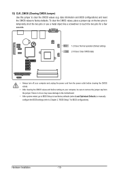
... jumper cap from the jumper. 12) CLR_CMOS (Clearing CMOS Jumper) Use this jumper to factory defaults. Failure to do so may cause damage to the motherboard. • After system restart, go to BIOS Setup to load factory defaults (select Load Optimized Defaults) or manually configure the BIOS settings (refer to Chapter...
... jumper cap from the jumper. 12) CLR_CMOS (Clearing CMOS Jumper) Use this jumper to factory defaults. Failure to do so may cause damage to the motherboard. • After system restart, go to BIOS Setup to load factory defaults (select Load Optimized Defaults) or manually configure the BIOS settings (refer to Chapter...


