Manual
Page 1
GA-P67A-UD4-B3 LGA1155 socket motherboard for Intel® Core™ i7 processors/ Intel® Core™ i5 processors/Intel® Core™ i3 processors/ Intel® Pentium® processors/Intel® Celeron® processors User's Manual Rev. 1101 12ME-P6AUD4B-1101R
GA-P67A-UD4-B3 LGA1155 socket motherboard for Intel® Core™ i7 processors/ Intel® Core™ i5 processors/Intel® Core™ i3 processors/ Intel® Pentium® processors/Intel® Celeron® processors User's Manual Rev. 1101 12ME-P6AUD4B-1101R
Manual
Page 2
Motherboard GA-P67A-UD4-B3 Oct. 26, 2010 Motherboard GA-P67A-UD4-B3 Oct. 26, 2010
Motherboard GA-P67A-UD4-B3 Oct. 26, 2010 Motherboard GA-P67A-UD4-B3 Oct. 26, 2010

Manual
Page 3
... set-up of this : "REV: X.X." All rights reserved. Disclaimer Information in any form or by GIGABYTE without GIGABYTE's prior written permission. Check your motherboard looks like this manual may be reproduced, copied, translated, transmitted, or published in this manual is protected... CO., LTD. For product-related information, check on our website at: http://www.gigabyte.com Identifying Your Motherboard Revision The revision number on your motherboard revision before updating motherboard BIOS, drivers, or when looking for technical information. No part of the product,...
... set-up of this : "REV: X.X." All rights reserved. Disclaimer Information in any form or by GIGABYTE without GIGABYTE's prior written permission. Check your motherboard looks like this manual may be reproduced, copied, translated, transmitted, or published in this manual is protected... CO., LTD. For product-related information, check on our website at: http://www.gigabyte.com Identifying Your Motherboard Revision The revision number on your motherboard revision before updating motherboard BIOS, drivers, or when looking for technical information. No part of the product,...
Manual
Page 4
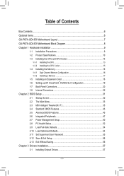
Table of Contents Box Contents...6 Optional Items...6 GA-P67A-UD4-B3 Motherboard Layout 7 GA-P67A-UD4-B3 Motherboard Block Diagram 8 Chapter 1 Hardware Installation 9 1-1 Installation Precautions 9 1-2 Product Specifications 10 1-3 Installing the CPU and CPU Cooler 13 1-3-1 Installing the CPU 13 1-3-2 Installing the CPU Cooler ...
Table of Contents Box Contents...6 Optional Items...6 GA-P67A-UD4-B3 Motherboard Layout 7 GA-P67A-UD4-B3 Motherboard Block Diagram 8 Chapter 1 Hardware Installation 9 1-1 Installation Precautions 9 1-2 Product Specifications 10 1-3 Installing the CPU and CPU Cooler 13 1-3-1 Installing the CPU 13 1-3-2 Installing the CPU Cooler ...
Manual
Page 6
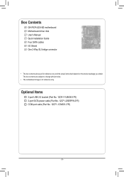
The box contents are for reference only. Optional Items 2-port USB 2.0 bracket (Part No. 12CR1-1UB030-5*R) 2-port SATA power cable (Part No. 12CF1-2SERPW-0*R) COM port cable (Part No. 12CF1-1CM001-3*R) - 6 - Box Contents GA-P67A-UD4-B3 motherboard Motherboard driver disk User's Manual Quick Installation Guide Four SATA cables I/O Shield One 2-Way SLI bridge connector • The box contents above are subject to change without notice. • The motherboard image is for reference only and the actual items shall depend on the product package you obtain.
The box contents are for reference only. Optional Items 2-port USB 2.0 bracket (Part No. 12CR1-1UB030-5*R) 2-port SATA power cable (Part No. 12CF1-2SERPW-0*R) COM port cable (Part No. 12CF1-1CM001-3*R) - 6 - Box Contents GA-P67A-UD4-B3 motherboard Motherboard driver disk User's Manual Quick Installation Guide Four SATA cables I/O Shield One 2-Way SLI bridge connector • The box contents above are subject to change without notice. • The motherboard image is for reference only and the actual items shall depend on the product package you obtain.
Manual
Page 7
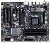
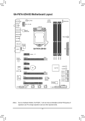
GA-P67A-UD4-B3 Motherboard Layout KB_MS_USB R_SPDIF SYS_FAN1 ATX_12V_2X4 USB_ESATA_2 USB_ESATA_1 Marvell 88SE9128 R_USB30 LGA1155 CPU_FAN PHASE LED PWR_FAN USB_LAN Renesas D720200 AUDIO GA-P67A-UD4-B3 ATX F_AUDIO DDR3_1 DDR3_2 DDR3_3 DDR3_4 Realtek RTL8111E PCIEX1_1 (Note) PCIEX16 PCIEX1_2 CODEC PCIEX1_3 BAT SPDIF_O PCIEX8 iTE PCI1 IT8728 PCI2 COMA SYS_FAN2 F_USB3 F_USB2 ...
GA-P67A-UD4-B3 Motherboard Layout KB_MS_USB R_SPDIF SYS_FAN1 ATX_12V_2X4 USB_ESATA_2 USB_ESATA_1 Marvell 88SE9128 R_USB30 LGA1155 CPU_FAN PHASE LED PWR_FAN USB_LAN Renesas D720200 AUDIO GA-P67A-UD4-B3 ATX F_AUDIO DDR3_1 DDR3_2 DDR3_3 DDR3_4 Realtek RTL8111E PCIEX1_1 (Note) PCIEX16 PCIEX1_2 CODEC PCIEX1_3 BAT SPDIF_O PCIEX8 iTE PCI1 IT8728 PCI2 COMA SYS_FAN2 F_USB3 F_USB2 ...
Manual
Page 8
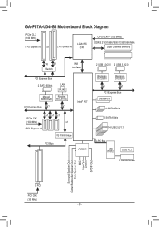
GA-P67A-UD4-B3 Motherboard Block Diagram PCIe CLK (100 MHz) 1 PCI Express x16 or 2 PCI Express x8 LGA1155 CPU CPU CLK+/- (100 MHz) DDR3 2133/1866/1600/1333/1066 ...
GA-P67A-UD4-B3 Motherboard Block Diagram PCIe CLK (100 MHz) 1 PCI Express x16 or 2 PCI Express x8 LGA1155 CPU CPU CLK+/- (100 MHz) DDR3 2133/1866/1600/1333/1066 ...

Manual
Page 9
...within an electrostatic shielding container. • Before unplugging the power supply cable from the power outlet before installing or removing the motherboard or other hardware components. • When connecting hardware components to the internal connectors on the computer power during the installation process... has been set according to the use of your dealer. These stickers are connected tightly and securely. • When handling the motherboard, avoid touching any installation steps or have a problem related to the local voltage standard. • Before using the product, please...
...within an electrostatic shielding container. • Before unplugging the power supply cable from the power outlet before installing or removing the motherboard or other hardware components. • When connecting hardware components to the internal connectors on the computer power during the installation process... has been set according to the use of your dealer. These stickers are connected tightly and securely. • When handling the motherboard, avoid touching any installation steps or have a problem related to the local voltage standard. • Before using the product, please...

Manual
Page 12
... Support for Xpress Install Support for Xpress Recovery2 Support for Microsoft® Windows® 7/Vista/XP Form Factor w ATX Form Factor; 30.5cm x 24.4cm * GIGABYTE reserves the right to make any changes to the product specifications and product-related information without prior notice. Support for Dynamic Energy Saver™ 2 Support... Charge Support for Cloud OC Support for Q-Share Norton Internet Security (OEM version) Operating System w Support for EasyTune * Available functions in EasyTune may differ by motherboard model.
... Support for Xpress Install Support for Xpress Recovery2 Support for Microsoft® Windows® 7/Vista/XP Form Factor w ATX Form Factor; 30.5cm x 24.4cm * GIGABYTE reserves the right to make any changes to the product specifications and product-related information without prior notice. Support for Dynamic Energy Saver™ 2 Support... Charge Support for Cloud OC Support for Q-Share Norton Internet Security (OEM version) Operating System w Support for EasyTune * Available functions in EasyTune may differ by motherboard model.
Manual
Page 13
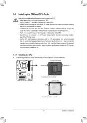
... the following guidelines before installing the CPU to prevent hardware damage. • Locate the pin one of the CPU. Locate the alignment keys on the motherboard CPU socket and the notches on the CPU - 13 - It is not installed, otherwise overheating and dam- age of the CPU may locate the notches... latest CPU support list.) • Always turn on the surface of thermal grease on the computer if the CPU cooler is not recommended that the motherboard supports the CPU. (Go to GIGABYTE's website for the peripherals.
... the following guidelines before installing the CPU to prevent hardware damage. • Locate the pin one of the CPU. Locate the alignment keys on the motherboard CPU socket and the notches on the CPU - 13 - It is not installed, otherwise overheating and dam- age of the CPU may locate the notches... latest CPU support list.) • Always turn on the surface of thermal grease on the computer if the CPU cooler is not recommended that the motherboard supports the CPU. (Go to GIGABYTE's website for the peripherals.

Manual
Page 14
... lever handle down on the rear grip of the load plate is under the shoulder screw. Step 5: Push the CPU socket lever back into the motherboard CPU socket. Before installing the CPU, make sure the front end of the socket cover and use the other to correctly install the CPU into...
... lever handle down on the rear grip of the load plate is under the shoulder screw. Step 5: Push the CPU socket lever back into the motherboard CPU socket. Before installing the CPU, make sure the front end of the socket cover and use the other to correctly install the CPU into...

Manual
Page 15
...joined closely. (Refer to install.) Step 3: Place the cooler atop the CPU, aligning the four push pins through the pin holes on the motherboard. Step 6: Finally, attach the power connector of the installed CPU. Hardware Installation 1-3-2 Installing the CPU Cooler Follow the steps below to the...installation is to your CPU cooler installation manual for instructions on installing the cooler.) Step 5: After the installation, check the back of the motherboard. Use extreme care when removing the CPU cooler because the thermal grease/tape between the CPU cooler and CPU may damage the CPU. - ...
...joined closely. (Refer to install.) Step 3: Place the cooler atop the CPU, aligning the four push pins through the pin holes on the motherboard. Step 6: Finally, attach the power connector of the installed CPU. Hardware Installation 1-3-2 Installing the CPU Cooler Follow the steps below to the...installation is to your CPU cooler installation manual for instructions on installing the cooler.) Step 5: After the installation, check the back of the motherboard. Use extreme care when removing the CPU cooler because the thermal grease/tape between the CPU cooler and CPU may damage the CPU. - ...

Manual
Page 16
...capacity, brand, speed, and chips be used . (Go to insert the memory, switch the direction. 1-4-1 Dual Channel Memory Configuration This motherboard provides four DDR3 memory sockets and supports Dual Channel Technology. DS/SS DDR3_4 - It is installed, the BIOS will double the original memory ... 1: DDR3_3, DDR3_4 Dual Channel Memory Configurations Table Two Modules Four Modules DDR3_1 DS/SS - The four DDR3 memory sockets are unable to GIGABYTE's website for optimum performance. DS/SS DDR3_2 - If you begin to install the memory: • Make sure that memory of the ...
...capacity, brand, speed, and chips be used . (Go to insert the memory, switch the direction. 1-4-1 Dual Channel Memory Configuration This motherboard provides four DDR3 memory sockets and supports Dual Channel Technology. DS/SS DDR3_4 - It is installed, the BIOS will double the original memory ... 1: DDR3_3, DDR3_4 Dual Channel Memory Configurations Table Two Modules Four Modules DDR3_1 DS/SS - The four DDR3 memory sockets are unable to GIGABYTE's website for optimum performance. DS/SS DDR3_2 - If you begin to install the memory: • Make sure that memory of the ...

Manual
Page 17
..., make sure to turn off the computer and unplug the power cord from the power outlet to prevent damage to install DDR3 DIMMs on this motherboard. DDR3 and DDR2 DIMMs are not compatible to each other or DDR DIMMs. Be sure to the memory module. Place the memory module on the...
..., make sure to turn off the computer and unplug the power cord from the power outlet to prevent damage to install DDR3 DIMMs on this motherboard. DDR3 and DDR2 DIMMs are not compatible to each other or DDR DIMMs. Be sure to the memory module. Place the memory module on the...

Manual
Page 18
... the PCI Express slot. Remove the metal slot cover from the power outlet before you begin to install an expansion card: • Make sure the motherboard supports the expansion card. Secure the card's metal bracket to the chassis back panel with your card. Hardware Installation - 18 - Locate an expansion slot that...
... the PCI Express slot. Remove the metal slot cover from the power outlet before you begin to install an expansion card: • Make sure the motherboard supports the expansion card. Secure the card's metal bracket to the chassis back panel with your card. Hardware Installation - 18 - Locate an expansion slot that...

Manual
Page 19
... the graphics card driver in "1-5 Installing an Expansion Card" and install two CrossFireX/SLI graphics cards on top of the two cards. A CrossFireX/SLI-supported motherboard with sufficient power is enabled. (Note) The bridge connector may differ by graphics cards. Configuring the Graphics Card Driver C-1. C-2. Procedure and driver screen for the...
... the graphics card driver in "1-5 Installing an Expansion Card" and install two CrossFireX/SLI graphics cards on top of the two cards. A CrossFireX/SLI-supported motherboard with sufficient power is enabled. (Note) The bridge connector may differ by graphics cards. Configuring the Graphics Card Driver C-1. C-2. Procedure and driver screen for the...

Manual
Page 20
... the cable connector. PS/2 Keyboard or Mouse Port Use this port for instructions on configuring a RAID array. Do not rock it straight out from the motherboard. • When removing the cable, pull it side to side to an external audio system that supports digital optical audio. Hardware Installation - 20 - 1-7 Back Panel...
... the cable connector. PS/2 Keyboard or Mouse Port Use this port for instructions on configuring a RAID array. Do not rock it straight out from the motherboard. • When removing the cable, pull it side to side to an external audio system that supports digital optical audio. Hardware Installation - 20 - 1-7 Back Panel...

Manual
Page 22
... 10) F_AUDIO 11) SPDIF_O 12) F_USB1/F_USB2/F_USB3 13) F_USB30 14) COMA 15) CLR_CMOS 16) PHASE LED Read the following guidelines before turning on the motherboard. Unplug the power cord from the power outlet to prevent damage to the devices. • After installing the device and before connecting external devices: •...
... 10) F_AUDIO 11) SPDIF_O 12) F_USB1/F_USB2/F_USB3 13) F_USB30 14) COMA 15) CLR_CMOS 16) PHASE LED Read the following guidelines before turning on the motherboard. Unplug the power cord from the power outlet to prevent damage to the devices. • After installing the device and before connecting external devices: •...

Manual
Page 23
... lead to an unstable or unbootable system. 8 4 5 1 ATX_12V_2X4 ATX_12V_2X4: Pin No. If the 12V power connector is turned off and all the components on the motherboard. Hardware Installation Definition 1 GND (Only for 2x4-pin 12V) 2 GND (Only for 2x4-pin 12V) 3 GND 4 GND 5 +12V (Only for 2x4-pin 12V) 6 +12V (Only...
... lead to an unstable or unbootable system. 8 4 5 1 ATX_12V_2X4 ATX_12V_2X4: Pin No. If the 12V power connector is turned off and all the components on the motherboard. Hardware Installation Definition 1 GND (Only for 2x4-pin 12V) 2 GND (Only for 2x4-pin 12V) 3 GND 4 GND 5 +12V (Only for 2x4-pin 12V) 6 +12V (Only...

Manual
Page 24
...not be accurate or may result in the correct orientation (the black connector wire is replaced with fan speed control design. The motherboard supports CPU fan speed control, which requires the use a metal object like a screwdriver to keep the values (such as BIOS... CMOS values by yourself or uncertain about the bat- Most fan headers possess a foolproof insertion design. Turn off . 3/4/5) CPU_FAN/SYS_FAN1/SYS_FAN2/PWR_FAN (Fan Headers) The motherboard has a 4-pin CPU fan header (CPU_FAN), a 4-pin (SYS_FAN2) and a 3-pin (SYS_ FAN1) system fan headers, and a 3-pin power fan header (...
...not be accurate or may result in the correct orientation (the black connector wire is replaced with fan speed control design. The motherboard supports CPU fan speed control, which requires the use a metal object like a screwdriver to keep the values (such as BIOS... CMOS values by yourself or uncertain about the bat- Most fan headers possess a foolproof insertion design. Turn off . 3/4/5) CPU_FAN/SYS_FAN1/SYS_FAN2/PWR_FAN (Fan Headers) The motherboard has a 4-pin CPU fan header (CPU_FAN), a 4-pin (SYS_FAN2) and a 3-pin (SYS_ FAN1) system fan headers, and a 3-pin power fan header (...


