
User Manual
Page 25
...PW+ PWSPEAK+ SPEAK- Note the positive and negative pins before connecting the cables. A front panel module mainly consists of power switch, reset switch, power LED, hard drive activity LED, speaker and etc. The LED is on when the system is detected at system startup. .... This function requires a chassis with a chassis intrusion switch/sensor. When connecting your system G using the power switch (refer to Chapter 2, "BIOS Setup," "Power Management," for more information). •• Speaker (Speaker): Connects to the pin assignments below. Message/Power/ Power Sleep LED Switch...
...PW+ PWSPEAK+ SPEAK- Note the positive and negative pins before connecting the cables. A front panel module mainly consists of power switch, reset switch, power LED, hard drive activity LED, speaker and etc. The LED is on when the system is detected at system startup. .... This function requires a chassis with a chassis intrusion switch/sensor. When connecting your system G using the power switch (refer to Chapter 2, "BIOS Setup," "Power Management," for more information). •• Speaker (Speaker): Connects to the pin assignments below. Message/Power/ Power Sleep LED Switch...

User Manual
Page 29
...) Use this jumper to factory defaults. Hardware Installation To clear the CMOS values, use a metal object like a screwdriver to Chapter 2, "BIOS Setup," for a few seconds. Open: Normal Short: Clear CMOS Values •• Always turn off your computer and unplug the power ...•• After system restart, go to BIOS Setup to load factory defaults (select Load Optimized Defaults) or manually configure the BIOS settings (refer to touch the two pins for BIOS configurations). - 29 - date information and BIOS configurations) and reset the CMOS values to clear the CMOS values ...
...) Use this jumper to factory defaults. Hardware Installation To clear the CMOS values, use a metal object like a screwdriver to Chapter 2, "BIOS Setup," for a few seconds. Open: Normal Short: Clear CMOS Values •• Always turn off your computer and unplug the power ...•• After system restart, go to BIOS Setup to load factory defaults (select Load Optimized Defaults) or manually configure the BIOS settings (refer to touch the two pins for BIOS configurations). - 29 - date information and BIOS configurations) and reset the CMOS values to clear the CMOS values ...
User Manual
Page 31
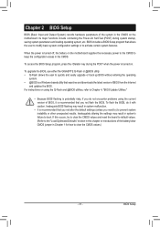
... try to clear the CMOS values and reset the board to default values. (Refer to the "Load Optimized Defaults" section in this chapter or introductions of the battery/clear CMOS jumper in Chapter 1 for how to boot. To flash the BIOS, do not encounter problems using the Q-Flash... do it is a Windows-based utility that you not flash the BIOS. To upgrade the BIOS, use either the GIGABYTE Q-Flash or @BIOS utility. •• Q-Flash allows the user to activate certain system features. BIOS includes a BIOS Setup program that allows the user to modify basic system configuration settings or...
... try to clear the CMOS values and reset the board to default values. (Refer to the "Load Optimized Defaults" section in this chapter or introductions of the battery/clear CMOS jumper in Chapter 1 for how to boot. To flash the BIOS, do not encounter problems using the Q-Flash... do it is a Windows-based utility that you not flash the BIOS. To upgrade the BIOS, use either the GIGABYTE Q-Flash or @BIOS utility. •• Q-Flash allows the user to activate certain system features. BIOS includes a BIOS Setup program that allows the user to modify basic system configuration settings or...

User Manual
Page 35
... reduce the useful life of these components. Incorrectly doing overclock/overvoltage may result in damage to boot. If this occurs, clear the CMOS values and reset the board to default values.) This section provides information on your overall system configurations. This page is for advanced users only and we recommend you...
... reduce the useful life of these components. Incorrectly doing overclock/overvoltage may result in damage to boot. If this occurs, clear the CMOS values and reset the board to default values.) This section provides information on your overall system configurations. This page is for advanced users only and we recommend you...

User Manual
Page 40
`` Channel A/B Timing Settings This sub-menu provides memory timing settings for each channel of memory. BIOS Setup - 40 - The respective timing setting screens are configurable only when DRAM Timing Selectable is set memory voltage. Note: Your system may become unstable or fail to boot after you to set to default values by loading optimized defaults or clearing the CMOS values. `` Advanced Voltage Settings This sub-menu allows you make changes on the memory timings. If this occurs, please reset the board to Quick or Expert.
`` Channel A/B Timing Settings This sub-menu provides memory timing settings for each channel of memory. BIOS Setup - 40 - The respective timing setting screens are configurable only when DRAM Timing Selectable is set memory voltage. Note: Your system may become unstable or fail to boot after you to set to default values by loading optimized defaults or clearing the CMOS values. `` Advanced Voltage Settings This sub-menu allows you make changes on the memory timings. If this occurs, please reset the board to Quick or Expert.

User Manual
Page 41
To clear the chassis intrusion status record, set Reset Case Open Status to Enabled, save the settings to the motherboard CI header. BIOS Setup If the system chassis cover is removed, this field will show "Yes", otherwise it will show "No" at next boot. && Case Open Displays... the detection status of previous chassis intrusion status and the Case Open field will show "No". `` PC Health Status && Reset Case Open Status...
To clear the chassis intrusion status record, set Reset Case Open Status to Enabled, save the settings to the motherboard CI header. BIOS Setup If the system chassis cover is removed, this field will show "Yes", otherwise it will show "No" at next boot. && Case Open Displays... the detection status of previous chassis intrusion status and the Case Open field will show "No". `` PC Health Status && Reset Case Open Status...

User Manual
Page 77
...for a non-RAID configuration. Intel(R) Rapid Storage Technology - Create RAID Volume If you press + , the MAIN MENU screen will appear (Figure 3). Reset Disks to enter the RAID Configuration Utility. Press + to Non-RAID [ MAIN MENU ] 4. Option ROM - 11.0.0.1339 Copyright(C) 2003-11 Intel .... Create RAID Volume 2. Figure 2 Step 2: After you want to create a RAID array, select Create RAID Volume in RAID BIOS Enter the RAID BIOS setup utility to configure a RAID array. Skip this step and proceed with the installation of Windows operating system for a message which...
...for a non-RAID configuration. Intel(R) Rapid Storage Technology - Create RAID Volume If you press + , the MAIN MENU screen will appear (Figure 3). Reset Disks to enter the RAID Configuration Utility. Press + to Non-RAID [ MAIN MENU ] 4. Option ROM - 11.0.0.1339 Copyright(C) 2003-11 Intel .... Create RAID Volume 2. Figure 2 Step 2: After you want to create a RAID array, select Create RAID Volume in RAID BIOS Enter the RAID BIOS setup utility to configure a RAID array. Skip this step and proceed with the installation of Windows operating system for a message which...

User Manual
Page 79
...Yes Type/Status(Vol ID) Member Disk(0) Member Disk(0) [hi]-Select [ESC]-Exit Figure 7 [ENTER]-Select Menu To exit the RAID BIOS utility, press or select 6. Option ROM - 11.0.0.1339 Copyright(C) 2003-11 Intel Corporation. Delete RAID Volume 3. When prompted to confirm ...]-Next [ESC]-Previous Menu Figure 6 [ENTER]-Select When completed, you can proceed to cancel (Figure 6). All Rights Reserved. 1. Create RAID Volume 2. Reset Disks to begin creating the RAID array. Appendix All Rights Reserved. [ CREATE VOLUME MENU ] Name : Volume0 RAID Level : RAID0(Stripe) Disks : ...
...Yes Type/Status(Vol ID) Member Disk(0) Member Disk(0) [hi]-Select [ESC]-Exit Figure 7 [ENTER]-Select Menu To exit the RAID BIOS utility, press or select 6. Option ROM - 11.0.0.1339 Copyright(C) 2003-11 Intel Corporation. Delete RAID Volume 3. When prompted to confirm ...]-Next [ESC]-Previous Menu Figure 6 [ENTER]-Select When completed, you can proceed to cancel (Figure 6). All Rights Reserved. 1. Create RAID Volume 2. Reset Disks to begin creating the RAID array. Appendix All Rights Reserved. [ CREATE VOLUME MENU ] Name : Volume0 RAID Level : RAID0(Stripe) Disks : ...


