
User Manual
Page 2
Motherboard G1.Sniper 5 Apr. 12, 2013 Motherboard G1.Sniper 5 Apr. 12, 2013
Motherboard G1.Sniper 5 Apr. 12, 2013 Motherboard G1.Sniper 5 Apr. 12, 2013

User Manual
Page 3
...example, "REV: 1.0" means the revision of the motherboard is the property of this manual may be made by copyright laws and is 1.0. Check your motherboard looks like this manual is protected by GIGABYTE without GIGABYTE's prior written permission. All rights reserved. Example: ...Changes to their respective owners. No part of GIGABYTE. For product-related information, check on our website at: http://www.gigabyte.com Identifying Your Motherboard Revision The revision number on your motherboard revision before updating motherboard BIOS, drivers, or when looking for technical ...
...example, "REV: 1.0" means the revision of the motherboard is the property of this manual may be made by copyright laws and is 1.0. Check your motherboard looks like this manual is protected by GIGABYTE without GIGABYTE's prior written permission. All rights reserved. Example: ...Changes to their respective owners. No part of GIGABYTE. For product-related information, check on our website at: http://www.gigabyte.com Identifying Your Motherboard Revision The revision number on your motherboard revision before updating motherboard BIOS, drivers, or when looking for technical ...
User Manual
Page 4
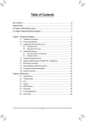
Table of Contents Box Contents...6 Optional Items...6 G1.Sniper 5 Motherboard Layout 7 G1.Sniper 5 Motherboard Block Diagram 8 Chapter 1 Hardware Installation 9 1-1 Installation Precautions 9 1-2 Product Specifications 10 1-3 Installing the CPU and CPU Cooler 13 1-3-1 Installing the CPU...13 1-3-2 Installing the CPU Cooler ...
Table of Contents Box Contents...6 Optional Items...6 G1.Sniper 5 Motherboard Layout 7 G1.Sniper 5 Motherboard Block Diagram 8 Chapter 1 Hardware Installation 9 1-1 Installation Precautions 9 1-2 Product Specifications 10 1-3 Installing the CPU and CPU Cooler 13 1-3-1 Installing the CPU...13 1-3-2 Installing the CPU Cooler ...
User Manual
Page 6
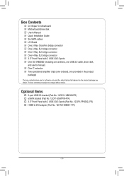
... (one onboard, one provided in the product package) The box contents above are subject to -DVI adapter (Part No. 12CT2-HDMI01-1*R) - 6 - Box Contents 55 G1.Sniper 5 motherboard 55 Motherboard driver disk 55 User's Manual 55 Quick Installation Guide 55 Six SATA cables 55 I/O Shield 55 One 2-Way CrossFire bridge connector 55 One 2-Way SLI...
... (one onboard, one provided in the product package) The box contents above are subject to -DVI adapter (Part No. 12CT2-HDMI01-1*R) - 6 - Box Contents 55 G1.Sniper 5 motherboard 55 Motherboard driver disk 55 User's Manual 55 Quick Installation Guide 55 Six SATA cables 55 I/O Shield 55 One 2-Way CrossFire bridge connector 55 One 2-Way SLI...
User Manual
Page 7
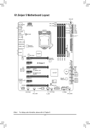
G1.Sniper 5 Motherboard Layout KB_MS_USB COAXIAL ATX_12V_2X4 R_USB30 HDMI DP_HDMI HP_PWR CPU_OPT CPU_FAN LGA1150 RST_SW PW_SW CMOS_SW SYS_FAN7 SYS_FAN6 VRIN VIOD VSA VAXG VIOA VRING VDIMM VCORE Debug LED (Note) USB30_LAN2 BIOS_SW USB30_LAN1 Renesas® uPD720210 AUDIO Intel® GbE LAN SYS_FAN1 PCIEX16_1 PEX8747 PCIEX1_1 G1.Sniper 5 Qualcomm® Atheros Killer E2201 LAN PCIEX8_1 PCIEX1_2 B_BIOS...
G1.Sniper 5 Motherboard Layout KB_MS_USB COAXIAL ATX_12V_2X4 R_USB30 HDMI DP_HDMI HP_PWR CPU_OPT CPU_FAN LGA1150 RST_SW PW_SW CMOS_SW SYS_FAN7 SYS_FAN6 VRIN VIOD VSA VAXG VIOA VRING VDIMM VCORE Debug LED (Note) USB30_LAN2 BIOS_SW USB30_LAN1 Renesas® uPD720210 AUDIO Intel® GbE LAN SYS_FAN1 PCIEX16_1 PEX8747 PCIEX1_1 G1.Sniper 5 Qualcomm® Atheros Killer E2201 LAN PCIEX8_1 PCIEX1_2 B_BIOS...
User Manual
Page 8
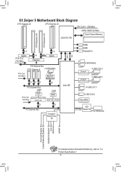
G1.Sniper 5 Motherboard Block Diagram 2 PCI Express x8 2 PCI Express x8 CPU CLK+/- (100 MHz) DDR3 1600/1333 MHz Dual Channel Memory LGA1150 CPU 1 PCI Express x16 1 PCI ...
G1.Sniper 5 Motherboard Block Diagram 2 PCI Express x8 2 PCI Express x8 CPU CLK+/- (100 MHz) DDR3 1600/1333 MHz Dual Channel Memory LGA1150 CPU 1 PCI Express x16 1 PCI ...

User Manual
Page 9
... strap, keep your hands dry and first touch a metal object to eliminate static electricity. •• Prior to installing the motherboard, please have a problem related to the use of electrostatic discharge (ESD). Hardware Installation If you are uncertain about any metal leads... electrostatic shielding container. •• Before unplugging the power supply cable from the power outlet before installing or removing the motherboard or other hardware components. •• When connecting hardware components to the internal connectors on the computer power during the ...
... strap, keep your hands dry and first touch a metal object to eliminate static electricity. •• Prior to installing the motherboard, please have a problem related to the use of electrostatic discharge (ESD). Hardware Installation If you are uncertain about any metal leads... electrostatic shielding container. •• Before unplugging the power supply cable from the power outlet before installing or removing the motherboard or other hardware components. •• When connecting hardware components to the internal connectors on the computer power during the ...

User Manual
Page 12
...2.0, SM BIOS 2.6, ACPI 2.0a Support for Q-Flash Support for Xpress Install Support for the software listed in APP Center may also differ depending on motherboard specifications. - @BIOS - USB Blocker Norton® Internet Security (OEM version) Intel® Rapid Start Technology Intel® Smart Connect Technology Intel&#...174; Smart Response Technology Support for Windows 8/7 Form Factor ŠŠ E-ATX Form Factor; 30.5cm x 26.4cm * GIGABYTE reserves the right to make any changes to the product specifications and product-related information without prior notice. * Please visit...
...2.0, SM BIOS 2.6, ACPI 2.0a Support for Q-Flash Support for Xpress Install Support for the software listed in APP Center may also differ depending on motherboard specifications. - @BIOS - USB Blocker Norton® Internet Security (OEM version) Intel® Rapid Start Technology Intel® Smart Connect Technology Intel&#...174; Smart Response Technology Support for Windows 8/7 Form Factor ŠŠ E-ATX Form Factor; 30.5cm x 26.4cm * GIGABYTE reserves the right to make any changes to the product specifications and product-related information without prior notice. * Please visit...

User Manual
Page 13
... socket and the notches on the computer if the CPU cooler is not recommended that the motherboard supports the CPU. (Go to GIGABYTE's website for the peripherals. It is not installed, otherwise overheating and damage of the CPU may occur. •• Set the CPU host frequency in ...
... socket and the notches on the computer if the CPU cooler is not recommended that the motherboard supports the CPU. (Go to GIGABYTE's website for the peripherals. It is not installed, otherwise overheating and damage of the CPU may occur. •• Set the CPU host frequency in ...

User Manual
Page 14
... handle down and away from the load plate during the process of the CPU. Follow the steps below to correctly install the CPU into the motherboard CPU socket. •• Before installing the CPU, make sure the front end of the CPU socket (or you may pop off the computer and...
... handle down and away from the load plate during the process of the CPU. Follow the steps below to correctly install the CPU into the motherboard CPU socket. •• Before installing the CPU, make sure the front end of the CPU socket (or you may pop off the computer and...

User Manual
Page 15
If the push pin is inserted as the picture above shows, the installation is to the CPU fan header (CPU_FAN) on the motherboard. Hardware Installation Inadequately removing the CPU cooler may adhere to the CPU. Push down each end of the heatsink, we recommend tubes with clamps, and...connector of the CPU cooler to install.) Step 3: Place the cooler atop the CPU, aligning the four push pins through the pin holes on the motherboard. •• For the waterblocks at each push pin. After connecting the tubes, make sure that the Male and Female push pins are attached to...
If the push pin is inserted as the picture above shows, the installation is to the CPU fan header (CPU_FAN) on the motherboard. Hardware Installation Inadequately removing the CPU cooler may adhere to the CPU. Push down each end of the heatsink, we recommend tubes with clamps, and...connector of the CPU cooler to install.) Step 3: Place the cooler atop the CPU, aligning the four push pins through the pin holes on the motherboard. •• For the waterblocks at each push pin. After connecting the tubes, make sure that the Male and Female push pins are attached to...

User Manual
Page 16
...DS/SS - - Dual Channel mode cannot be used . (Go to GIGABYTE's website for the latest supported memory speeds and memory modules.) ••...before you begin to insert the memory, switch the direction. 1-4-1 Dual Channel Memory Configuration This motherboard provides four DDR3 memory sockets and supports Dual Channel Technology. When enabling Dual Channel mode with two memory... modules, we recommend that the motherboard supports the memory. It is recommended that memory of the same capacity, brand, speed, and ...
...DS/SS - - Dual Channel mode cannot be used . (Go to GIGABYTE's website for the latest supported memory speeds and memory modules.) ••...before you begin to insert the memory, switch the direction. 1-4-1 Dual Channel Memory Configuration This motherboard provides four DDR3 memory sockets and supports Dual Channel Technology. When enabling Dual Channel mode with two memory... modules, we recommend that the motherboard supports the memory. It is recommended that memory of the same capacity, brand, speed, and ...

User Manual
Page 17
... left, place your memory modules in the memory sockets. Follow the steps below to the memory module. Hardware Installation Place the memory module on this motherboard. Spread the retaining clip at the right end of the memory, push down on the memory and insert it can only fit in one direction...
... left, place your memory modules in the memory sockets. Follow the steps below to the memory module. Hardware Installation Place the memory module on this motherboard. Spread the retaining clip at the right end of the memory, push down on the memory and insert it can only fit in one direction...
User Manual
Page 18
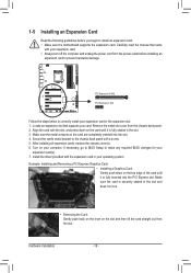
... card until it is fully inserted into the slot. 4. If necessary, go to BIOS Setup to install an expansion card: •• Make sure the motherboard supports the expansion card. 1-5 Installing an Expansion Card Read the following guidelines before installing an expansion card to prevent hardware damage. Remove the metal slot...
... card until it is fully inserted into the slot. 4. If necessary, go to BIOS Setup to install an expansion card: •• Make sure the motherboard supports the expansion card. 1-5 Installing an Expansion Card Read the following guidelines before installing an expansion card to prevent hardware damage. Remove the metal slot...

User Manual
Page 19
A CrossFire/SLI-supported motherboard with your graphics cards for the power requirement) B. For the latest GPU support information, please refer to the AMD VISION Engine Control Center. To Enable ...
A CrossFire/SLI-supported motherboard with your graphics cards for the power requirement) B. For the latest GPU support information, please refer to the AMD VISION Engine Control Center. To Enable ...

User Manual
Page 20
... to 192KHz/24bit 8-channel LPCM audio output. It also supports up to an external audio system that your device and then remove it from the motherboard. •• When removing the cable, pull it straight out from Windows 8.) In Windows 8, select All apps>Control Panel>Hardware and Sound>Sound>Playback, set...
... to 192KHz/24bit 8-channel LPCM audio output. It also supports up to an external audio system that your device and then remove it from the motherboard. •• When removing the cable, pull it straight out from Windows 8.) In Windows 8, select All apps>Control Panel>Hardware and Sound>Sound>Playback, set...

User Manual
Page 21
... Mbps data rate Activity LED: State Blinking Off Description Data transmission or receiving is occurring No data transmission or receiving is recommended that you install motherboard drivers in a 5.1-channel audio configuration. Line In The default line out jack. Before using this audio jack to connect rear speakers in Chapter 6, "Configuring 2/5.1-Channel...
... Mbps data rate Activity LED: State Blinking Off Description Data transmission or receiving is occurring No data transmission or receiving is recommended that you install motherboard drivers in a 5.1-channel audio configuration. Line In The default line out jack. Before using this audio jack to connect rear speakers in Chapter 6, "Configuring 2/5.1-Channel...
User Manual
Page 22
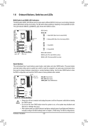
Voltage measurement points(G1.Sniper 3) Voltage measurement points(G1.Sniper 3) DDIIPP 11 22 33 44 DDIIPP 11 22 33 44 DIP 1 234 DIP 1 234 MBIOS_LED BBIOS_LED PCIe Control (Z87X-UP7) DIP 1 234 PCIe Control (Z87X-... which BIOS is active) DDIIPP 11 22 33 PCIe power connector (SATA)(X58A-OC) DDIIPP 11 22 33 DDIIPP 11 22 33 Quick Buttons This motherboard has 3 quick buttons: power button, reset button and clear CMOS button. Voltage measurement module(X58A-OC) PCIe power connector (SATA)(X58A-OC) DIP 1 23 PWM...
Voltage measurement points(G1.Sniper 3) Voltage measurement points(G1.Sniper 3) DDIIPP 11 22 33 44 DDIIPP 11 22 33 44 DIP 1 234 DIP 1 234 MBIOS_LED BBIOS_LED PCIe Control (Z87X-UP7) DIP 1 234 PCIe Control (Z87X-... which BIOS is active) DDIIPP 11 22 33 PCIe power connector (SATA)(X58A-OC) DDIIPP 11 22 33 DDIIPP 11 22 33 Quick Buttons This motherboard has 3 quick buttons: power button, reset button and clear CMOS button. Voltage measurement module(X58A-OC) PCIe power connector (SATA)(X58A-OC) DIP 1 23 PWM...

User Manual
Page 24
... sure your devices are compliant with the connectors you wish to connect. •• Before installing the devices, be sure to the connector on the motherboard. Unplug the power cord from the power outlet to prevent damage to the devices. •• After installing the device and before connecting external devices...
... sure your devices are compliant with the connectors you wish to connect. •• Before installing the devices, be sure to the connector on the motherboard. Unplug the power cord from the power outlet to prevent damage to the devices. •• After installing the device and before connecting external devices...

User Manual
Page 25
... power supply cable to an unstable or unbootable system. 5 8 1 4 ATX_12V_2X4 ATX_12V_2X4: Pin No. If a power supply is turned off and all the components on the motherboard. 1/2) ATX_12V_2X4/ATX (2x4 12V Power Connector and 2x12 Main Power Connector) With the use of the power connector, the power supply can supply enough stable...
... power supply cable to an unstable or unbootable system. 5 8 1 4 ATX_12V_2X4 ATX_12V_2X4: Pin No. If a power supply is turned off and all the components on the motherboard. 1/2) ATX_12V_2X4/ATX (2x4 12V Power Connector and 2x12 Main Power Connector) With the use of the power connector, the power supply can supply enough stable...


