Hardware Manual
Page 1
... utilizar este producto. Portal de Gamarra 36, Pabellón, 32 01013 Vitoria (Alava)-APDO 133, Spain Phone 945-283588 Designed by ALPINE Japan Printed in Japan (Y) 68-02065Z14-A R NVE-N872A Satellite Linked Navigation HARDWARE MANUAL Please read before using this product. LTD. Paris Nord Il, B.P. 50016, 95945 Roissy Charles de Gaulle Cedex, France Phone...
... utilizar este producto. Portal de Gamarra 36, Pabellón, 32 01013 Vitoria (Alava)-APDO 133, Spain Phone 945-283588 Designed by ALPINE Japan Printed in Japan (Y) 68-02065Z14-A R NVE-N872A Satellite Linked Navigation HARDWARE MANUAL Please read before using this product. LTD. Paris Nord Il, B.P. 50016, 95945 Roissy Charles de Gaulle Cedex, France Phone...
Hardware Manual
Page 13
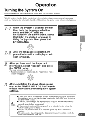
... the ignition key is displayed. Then press the ENTER button. a NVE-N872A power is turned on page 11. a If the disc cannot be read this system, when the display monitor is set in the navigation display mode or external input display mode and the ignition key is ...may discharge. a Operation varies depending upon the disc version in the navigation system, "Please insert DVD-ROM" is displayed. For details, refer to an authorized Alpine dealer. a If there is no disc in use. Operation Turning the System On (The display examples are displayed on with each language. 2...
... the ignition key is displayed. Then press the ENTER button. a NVE-N872A power is turned on page 11. a If the disc cannot be read this system, when the display monitor is set in the navigation display mode or external input display mode and the ignition key is ...may discharge. a Operation varies depending upon the disc version in the navigation system, "Please insert DVD-ROM" is displayed. For details, refer to an authorized Alpine dealer. a If there is no disc in use. Operation Turning the System On (The display examples are displayed on with each language. 2...
Installation Guide
Page 1
R Satellite Linked Navigation NVE-N872A Guide for Installation and Connections English Guide d'installation et de connexion Français Guía de instalación y conexiones Español
R Satellite Linked Navigation NVE-N872A Guide for Installation and Connections English Guide d'installation et de connexion Français Guía de instalación y conexiones Español

Installation Guide
Page 8
...Stopper Navigation side lead Pliers Parking Brake Lead Connection PARKING BRAKE NVE-N872A (Yellow/Blue) Pinch Connector Parking brake lamp Parking brake lead Parking brake switch Battery Chassis Connection Diagram of SPST Switch (Sold Separately) (If the ACC power supply is not available) NVE-N872A (... the fuse amperage shown above are in systems where the NVE-N872A is used individually. • If the switched power (ignition) lead of the NVE-N872A is connected directly to the positive (+) terminal of the vehicle's battery, the NVE-N872A draws some cases, this case, contents of...
...Stopper Navigation side lead Pliers Parking Brake Lead Connection PARKING BRAKE NVE-N872A (Yellow/Blue) Pinch Connector Parking brake lamp Parking brake lead Parking brake switch Battery Chassis Connection Diagram of SPST Switch (Sold Separately) (If the ACC power supply is not available) NVE-N872A (... the fuse amperage shown above are in systems where the NVE-N872A is used individually. • If the switched power (ignition) lead of the NVE-N872A is connected directly to the positive (+) terminal of the vehicle's battery, the NVE-N872A draws some cases, this case, contents of...
Installation Guide
Page 10
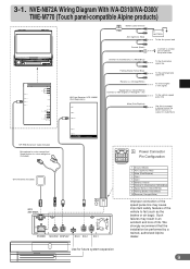
... and loss of the vehicle to a metal part of chassis body with screw To the Illumination signal line POWER SUPPLY REMOTE IN / OUT NAVIGATION IN DISPLAY OUT SUBW. PRE IN/OUT REAR FRONT L R Ai-NET EXT.OUT AV SELECTOR AUX OUT CAMERA IN VIDEO L AUDIO R... 13P RGB Extension Cable Included Microphone for voice recognition/ Speak button for future system expansion 9 Such failures may cause important safety features of life. NVE-N872A Wiring Diagram With IVA-D310/IVA-D300/ TME-M770 (Touch panel-compatible Alpine products) (10A) Battery Lead (Yellow) ACC (Ignition) (Red) BATTERY ...
... and loss of the vehicle to a metal part of chassis body with screw To the Illumination signal line POWER SUPPLY REMOTE IN / OUT NAVIGATION IN DISPLAY OUT SUBW. PRE IN/OUT REAR FRONT L R Ai-NET EXT.OUT AV SELECTOR AUX OUT CAMERA IN VIDEO L AUDIO R... 13P RGB Extension Cable Included Microphone for voice recognition/ Speak button for future system expansion 9 Such failures may cause important safety features of life. NVE-N872A Wiring Diagram With IVA-D310/IVA-D300/ TME-M770 (Touch panel-compatible Alpine products) (10A) Battery Lead (Yellow) ACC (Ignition) (Red) BATTERY ...
Installation Guide
Page 12
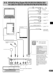
...(such as the brakes or air bags). We strongly recommend that the installation be performed by a trained, authorized Alpine dealer. NVE-N872A Wiring Diagram With IVA-D901/IVA-D900/IVA-C801/ IVA-C800/CVA-1006/CVA-1005/TME-M790/TME-M760/TME...-M750A (10A) Battery Lead (Yellow) ACC (Ignition) (Red) BATTERY To the Acc power lead POWER SUPPLY REMOTE IN/OUT NAVIGATION ...Mute 13P RGB Extension Cable Included Microphone for voice recognition/ Speak button for future system expansion 11 3-3.
...(such as the brakes or air bags). We strongly recommend that the installation be performed by a trained, authorized Alpine dealer. NVE-N872A Wiring Diagram With IVA-D901/IVA-D900/IVA-C801/ IVA-C800/CVA-1006/CVA-1005/TME-M790/TME-M760/TME...-M750A (10A) Battery Lead (Yellow) ACC (Ignition) (Red) BATTERY To the Acc power lead POWER SUPPLY REMOTE IN/OUT NAVIGATION ...Mute 13P RGB Extension Cable Included Microphone for voice recognition/ Speak button for future system expansion 11 3-3.

Installation Guide
Page 13
... washer (M4×8) 3. 1 3 3 2 Mount the unit on either side. Air ventilation hole (Rear of NVE-N872A) Note: The main unit must be facing the navigation unit. 2 Press the Navigation unit onto the Velcro fastener at the mounting position. Continued to step 5 "Securing leads, etc." 5 (Bottom side...spring washers (M6) 6, and wing nuts (M6) 8. Mounting Caution Do not block the unit's fan, thus preventing air circulation. Press the Navigation unit onto the mounting location. Mount the brackets at both sides of the unit with screws with flanged self-tapping screws (M5×15) ...
... washer (M4×8) 3. 1 3 3 2 Mount the unit on either side. Air ventilation hole (Rear of NVE-N872A) Note: The main unit must be facing the navigation unit. 2 Press the Navigation unit onto the Velcro fastener at the mounting position. Continued to step 5 "Securing leads, etc." 5 (Bottom side...spring washers (M6) 6, and wing nuts (M6) 8. Mounting Caution Do not block the unit's fan, thus preventing air circulation. Press the Navigation unit onto the mounting location. Mount the brackets at both sides of the unit with screws with flanged self-tapping screws (M5×15) ...


